DLBA UNIVERSITY
A CFD Analysis of Fluid Flow in Ventilation and Exhaust Systems of Gas Turbine Driven, High-Speed Light Craft
SEPTEMBER 28, 2020
By
Paul Sunderaj Martin, Det Norske Veritas
James A. Supan, DLBA Naval Architects
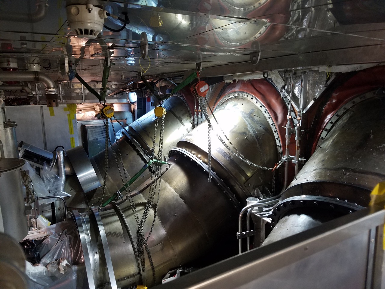
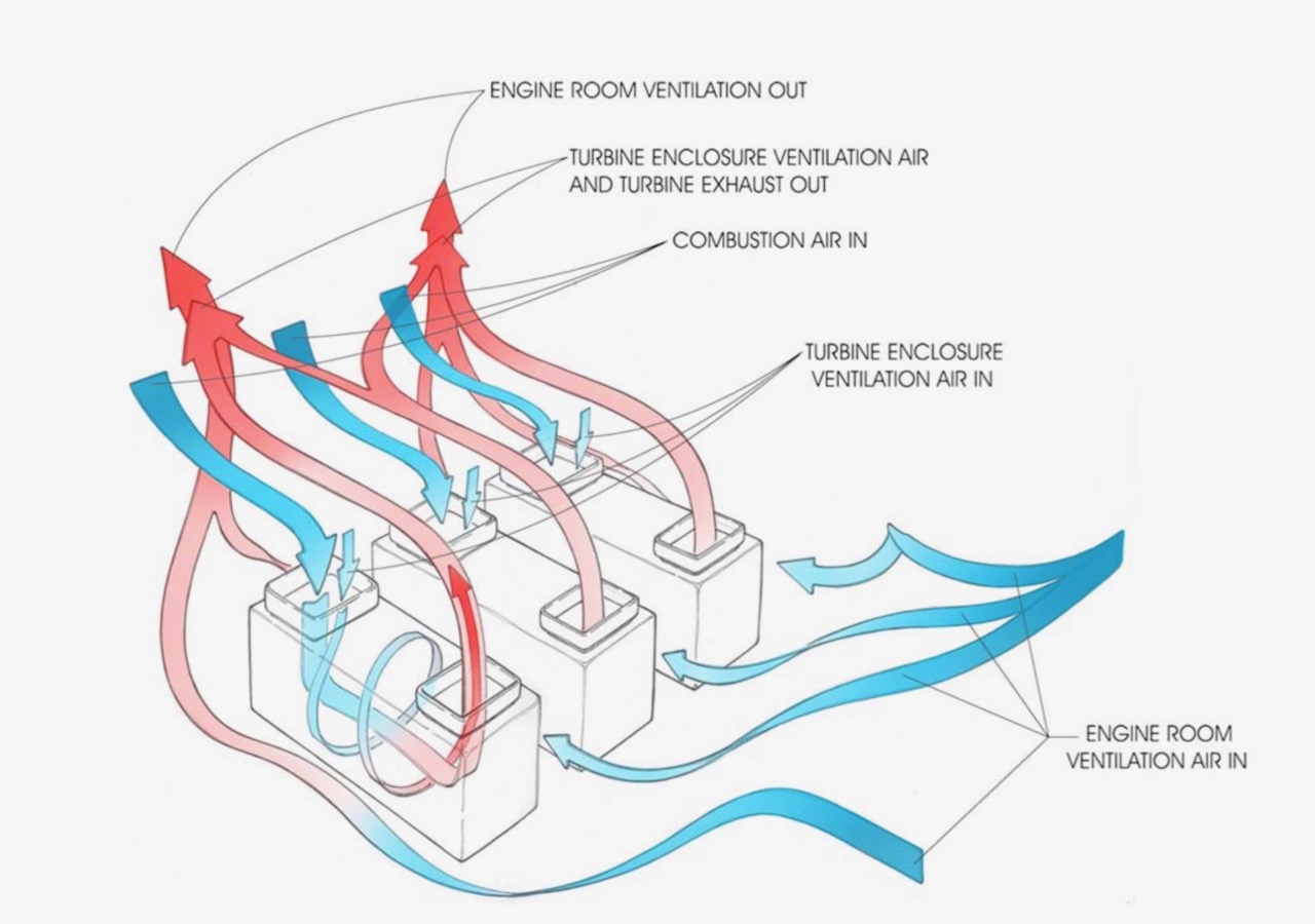
The two fastest yacht projects we’ve collaborated on at DLBA stand out from the norm due to the use of gas turbine power plants. In this paper, we outline the engineering effort undertaken to develop the gas turbine exhaust and machinery space ventilation system for one of these special projects. Gas turbines are special machines which are extremely powerful when compared to a typical diesel engine of the same weight. This unmatched power density, when coupled with waterjets, is currently the best solution for propelling large yachts at high speed. Some vessels have a single gas turbine and waterjet to provide a nudge of extra speed, however the projects we’ve had the opportunity to support have had a gas turbine for each driveline. Integrating these fire-breathing beasts into a yacht is a challenging process, with a number of factors to consider, such as heat, thermal growth, noise, and most-importantly, combustion air intakes and exhaust gas outlets. Gas turbines consume much more air than diesel engines so integrating suitably-sized ducting into the vessel to achieve acceptable airflow is key to success.

Summary
It is clear that what appeared to be a simple problem (standard yacht ventilation design) was not easy to solve. As of this date, there are no classification requirements for the design of engine room ventilation systems, with the exception of a statement that the engine temperature should not exceed a certain limit, which is a personnel environment limit (113°F/45°C). This temperature limit also provides a margin of protection for sensitive equipment which has high temperature compartment operation requirements usually limited to around 131°F (55°C). While in typical yacht designs there are normally no problems with temperatures in the engine room, in this case it is the high power density and a high power volume ratio of the propulsion units that has contributed to the high engine room temperature.

Figure: Original Engine Room Layout
As yacht designers and naval architects start to incorporate higher power diesels and more gas turbines into their designs to achieve better performance, we predict computational tools such as CFD analysis will become more commonplace.
Once an engineering challenge presents itself, whether it be ventilation cooling, exhaust gas flow, or evaluation of air flow over exterior surfaces (which is starting to replace empirical testing done in wind tunnels), it is best to team with a specialist in this field. Start-up costs associated with computers, software and training can be prohibitive for a few one-off designs. In addition, the old adage GIGO (garbage in – garbage out) proves truer than ever before. Using a specialist experienced in the applications of CFD will help novice users avoid fundamental errors in model development and the establishment of boundary conditions.
Use of CFD analysis is finding its way into the naval engineering market place and can provide an effective method for the development of detail design projects prior to construction or, as in this case, an effective means for troubleshooting an existing problem.
In case you would like to receive the full paper, or discuss about this subject, please contact Jeffrey Bowles.
References
- Taggart, Robert ed., Ship Design and Construction, The Society of Naval Architects and Marine Engineers, 1980.
- Harrington, Roy L., Marine Engineering, The Society of Naval Architects and Marine Engineers, 1992.
- SNAME, Recommended Practices for Merchant Ship Heating, Ventilation and Air Conditioning Design Calculations, T&R Bulletin 4-16, August 1980.
Share this article online:
HOW CAN WE HELP YOU?
FEEL FREE TO CONTACT US

DLBA Naval Architects
860 Greenbrier Circle, Suite 201 Chesapeake, Virginia 23320 USA
Phone: 757-545-3700 | Fax: 757-545-8227 | dlba@gibbscox.com
STAY UPDATED
SIGN UP FOR OUR NEWSLETTER
Keep your finger on the pulse of the latest points of focus in naval architecture and engineering: subscribe to DLBA’s concise monthly newsletter. Within it, we briefly describe and picture our latest projects and concepts. We encourage feedback and seek to have our newsletter spark conversation regarding potential collaborations and further advancements as we share our passion for the industry.
