
DLBA UNIVERSITY
Resistance Characteristics of Semi-Displacement Mega Yacht Hull Forms
SEPTEMBER 18, 2019
By D.L. Blount and J. A. McGrath, DLBA Naval Architects, USA
The combination of increasing vessel size and higher speed requirements are driving hull form design into new areas (think of the new launch by SilverYachts’ recent launch of M/Y BOLD, the 85m fast explorer capable of 24 knots). In this expanded trade space where decisions are made regarding hull form, there are lots of options. Potential hull forms include round bilge, hard chine, and double chine hull forms. Because these hull form types are classified or characterized differently in their traditional naval architectural coefficients, the need exists to create a universal metric for the comparison of the different shapes and their relative performance. DLBA undertook a study to identify and summarize the different systematic hull form series available in the public domain. The results of this study are captured in this technical paper by Blount & McGrath. Perhaps the most significant conclusion is that, for minimum resistance, irrespective of the hull form, the slenderness ratio of the hull (L/∇1/3) should be kept above 6.5 for minimum resistance when operating at speeds in the semi-displacement regime.
In case you would like to receive the full paper, or discuss about this subject, please contact Jeffrey Bowles.
ABSTRACT
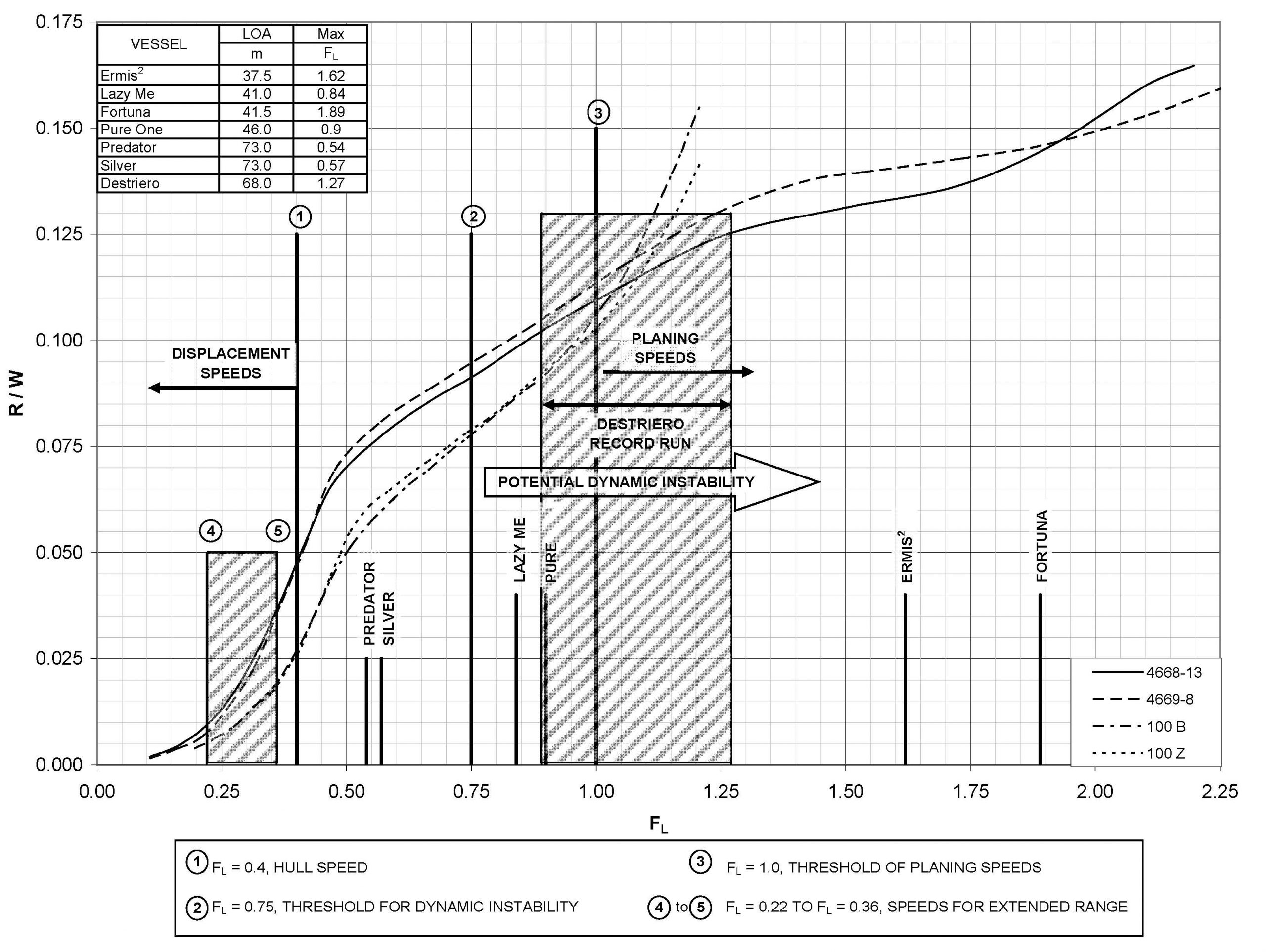
Mega yachts are growing in scale. The combination of cruise and maximum speeds, along with increase in hull lengths result in operational Froude numbers, FL, between 0.3 and 1.0. The concentration of current mega yacht projects have FL between 0.3 and 0.6 with few approaching FL = 1.0. Hull forms with different transverse sections show a variation in resistance characteristics for similar slenderness ratios in this range of Froude numbers. Resistance values among other geometric considerations are sensitive to slenderness ratio and longitudinal center of gravity, LCG. On occasion, LCG shifts, stern wedges and bulbous bows are techniques being employed to achieve minimum resistance for traditional displacement hull forms. However, these techniques need to be approached with caution as transverse instabilities can result at speeds greater than 22 to 25 knots. Hull form variants incorporating flow-separating spray rails become significant at high speeds. 500 mt was selected as being representative of a typical displacement for mega yachts. Model test data were scaled to make comparisons and analyses of bare hull resistance of many available experimental hull series. Thus, this paper addresses resistance variations related to different hull forms, slenderness ratio and other hull characteristics along with suggested design criteria for forecasting the threshold of dynamic transverse stability.
REFERENCES
1. NORDSTROM, H.F., ‘Some Tests With Models of Small Vessels’, SSPA Report No. 19, 1951.
2. BARNABY, K.C., ‘Basic Naval Architecture’, Hutchinson Scientific and Technical, London, 6th Edition, November 1969.
3. TAYLOR, D.W., ‘The Speed and Power of Ships’, 3rd Edition, U.S. Government Printing Office, 1943.
4. GERTLER, M., ‘A Reanalysis of the Original Test Data for the Taylor Standard Series’, David Taylor Model Basin Report 806, March 1954.
5. GRAFF, W., KRACHT, A. AND WEINBLUM, G. ‘Some Extensions of D.W. Taylor’s Standard Series’, SNAME Transactions, 1964.
6. YEH, H.Y.H., ‘Series 64 Resistance Experiments on High-Speed Displacement Forms’, Marine Technology, July 1965.
7. MARWOOD, W.J. AND BAILEY, D., ‘Design Data for High-Speed Displacement Hulls of Round-Bilge Form’, National Physical Laboratory, Report 99, February 1969.
8. LASKY, M.P., ‘Performance of High-Speed Naval Ships, Part II: Results of Resistance Tests
in Smooth Water on Nine Hull Forms (LCB/LCG Effect)’, NSRDC Report C-3311, November 1970. Approved for Public Release
9. BAILEY, D., ‘Performance Prediction – Fast Craft’, RINA Occasional Publication No. 1, November 1974.
10. BAILEY, D., ‘The NPL High Speed Round Bilge Displacement Hull Series’, Maritime Technology Monograph, No. 4, 1976.
11. BEYS, P.M., ‘Series 63 – Round Bottom Boats’, Stevens Institute of Technology, Davidson Laboratory Report 949, 1993.
12. GRIGOROPOULOS, G.J. AND LOUKAKIS, T.A., ‘Resistance of Double-Chine, Large, High-Speed Craft’, Bulletin de L’Association Technique Maritime et Aeronautique, ATMA Vol. 99, Paris, June 1999.
13. RADOJCIC, D., GRIGOROPOULOS, G.D., RODIC, T., KUVELIC, T., and DAMALA, D.P., ‘The Resistance and Trim of SemiDisplacement, Double Chine, Transom-Stern Hull Series’, FAST 2001, Vol. III, 2001.
14. CLEMENT, E.P. AND BLOUNT, D.L., ‘Resistance Tests of a Systematic Series of Planing Hull Forms’, SNAME Transactions, 1963.
15. KEUNING, J.A. AND GERRITSMA, J., ‘Resistance Tests of a Series of Planing Hull Forms with 25 Degrees Dead-Rise Angle’, ISP, Vol. 29, No. 337, September 1982.
16. KOWALYSHYN, D.H. AND METCALF, B., ‘A USCG Systematic Series of High Speed Planing Hulls’, SNAME Transactions, 2006.
17. GERTLER, M., ‘The Prediction of Effective Horsepower of Ships by Methods in Use at the David Taylor Model Basin’, David Taylor Model Basin Report 576, December 1947.
18. SCHOLARS, R.E., ‘An Investigation of the Performance Characteristics of a Long, Slender Hull’, Trident Scholar Report, U.S. Naval Academy, May 1968.
19. MARWOOD, W.J. AND BAILEY, D., Transverse Stability of Round-Bottomed High Speed Craft Underway’, NPL Ship Report 98, October 1968.
20. BLOUNT, D.L. AND CODEGA. L.T., ‘Dynamic stability of Planing Boats’, Marine Technology, January 1992.
21. RIDGELY-NEVITT, ‘The Resistance of a High Displacement-Length Ratio Trawler Series’, SNAME Transactions, 1967
Share this article online:
Share on facebook
Share on linkedin
Share on twitter
Share on whatsapp
HOW CAN WE HELP YOU?
FEEL FREE TO CONTACT US

DLBA Naval Architects
860 Greenbrier Circle, Suite 201 Chesapeake, Virginia 23320 USA
Phone: 757-545-3700 | Fax: 757-545-8227 | dlba@gibbscox.com
STAY UPDATED
SIGN UP FOR OUR NEWSLETTER
Keep your finger on the pulse of the latest points of focus in naval architecture and engineering: subscribe to DLBA’s concise monthly newsletter. Within it, we briefly describe and picture our latest projects and concepts. We encourage feedback and seek to have our newsletter spark conversation regarding potential collaborations and further advancements as we share our passion for the industry.